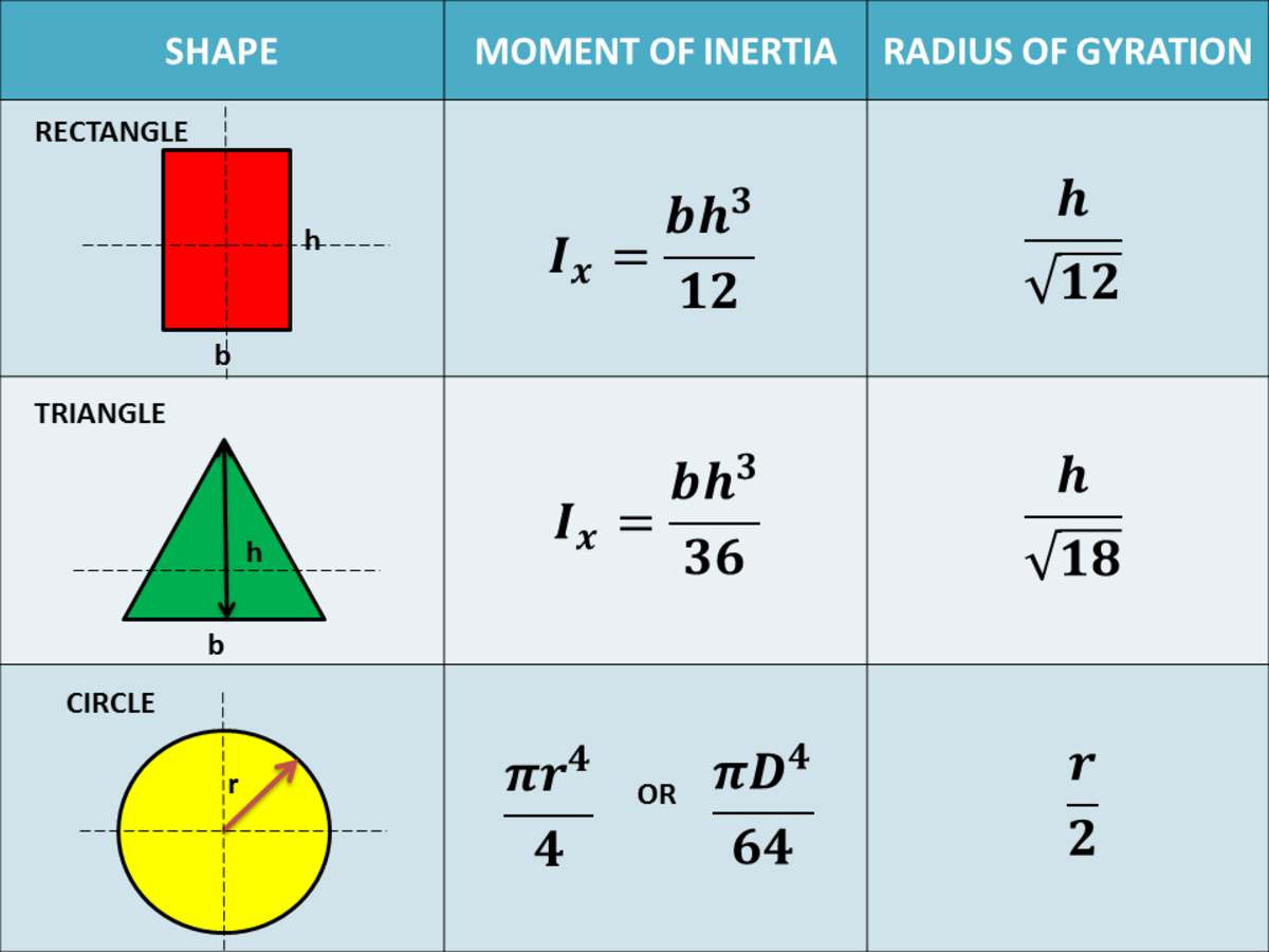

$I$ appears in the equation that gives the critical load at which a column will buckle. The area moment of inertia is an important parameter for any application that which involves bending of a structural member, which means it appears constantly in the analysis of beams and columns. Applications of the Area Moment of Inertia $$I_x = b\left[ \frac$ in the example above) correspond to the correct bending axis, or else you will first need to apply the parallel axis theorem to get $I$ values for the correct axis. To calculate $I_x$ all we have to do is integrate from the bottom of the rectangle at $y = -h/2$ to the top of the rectangle at $y = h/2$. Because the $y$ term is squared, the strips further away from the bending axis (the $x$ axis) contribute much more to $I$ than those close to the axis. This is why we are integrating – to calculate the effect of all of these really small strips. $I_x$ is given by the following equation:Įach strip contributes to the area moment of inertia. This is one of the reasons the I-beam is such a commonly used cross-section for structural applications – most of the material is located far from the bending axis, which makes it very efficient at resisting bending whilst using a minimal amount of material. Let’s compare $I$ values calculated for a few different cross-sections, for the bending axis shown below: Area moment of inertia values (in mm 4) for three shapesĬross-sections that locate the majority of the material far from the bending axis have larger moments of inertia – it is more difficult to bend them. It’s not a unique property of a cross section – it varies depending on the bending axis that is being considered. It reflects how the area of the cross section is distributed relative to a particular axis. It is denoted using the letter $I$, has units of length to the fourth power, which is typically $mm^4$ or $in^4$. This resistance to bending can be quantified by calculating the area moment of inertia of the cross-section. As we will soon see, this is related to the area moment of inertia. The same plank is much less stiff when the load is applied to the long edge of the cross-section. The plank on the left has more material located further from the bending axis, which makes it much stiffer. This is because resistance to bending depends on how the material of the cross-section is distributed relative to the bending axis. The plank will be much less stiff when the load is placed on the longer edge of the cross-section.

Integrating curvatures over beam length, the deflection, at some point along x-axis, should also be reversely proportional to I.Video can’t be loaded because JavaScript is disabled: Understanding the Area Moment of Inertia ()Ĭonsider a thin plank that supports a 100 kg load. Therefore, it can be seen from the former equation, that when a certain bending moment M is applied to a beam cross-section, the developed curvature is reversely proportional to the moment of inertia I. Beam curvature κ describes the extent of flexure in the beam and can be expressed in terms of beam deflection w(x) along longitudinal beam axis x, as: \kappa = \frac.

Where E is the Young's modulus, a property of the material, and κ the curvature of the beam due to the applied load. The bending moment M applied to a cross-section is related with its moment of inertia with the following equation: The moment of inertia (second moment or area) is used in beam theory to describe the rigidity of a beam against flexure (see beam bending theory). The term second moment of area seems more accurate in this regard. This is different from the definition usually given in Engineering disciplines (also in this page) as a property of the area of a shape, commonly a cross-section, about the axis. It is related with the mass distribution of an object (or multiple objects) about an axis. In Physics the term moment of inertia has a different meaning. The dimensions of moment of inertia (second moment of area) are ^4.


 0 kommentar(er)
